Some of our work involves reviewing design drawings prepared by architects and other design professionals. Over the years we have seen many examples of both good and poor design. Most of the poor designs appear to be the result of designers not understanding how vehicles move, and not understanding how to design for moving vehicles.
A key tool for designing for vehicle movement is a vehicle turning template, although in most cases these fixed templates have been superseded by computer-generated swept-path analysis. This article is intended to help designers provide for vehicle movement in their design by using tracking curves templates.
How vehicles move
Any wheeled vehicle requires more space when turning through a curve than it does when travelling in a straight line. How much space depends on a variety of factors.
Almost all cars have one fixed rear axle and one front axle with steered wheels. The steering uses geometry based on the Ackermann system so that the steered wheels on the inside and outside of the turn follow a different radius as the vehicle turns. The centre of the curve is positioned somewhere along the extension of the rear axle, as shown in the diagram.
It can be seen from the diagram that all four wheels follow a different radius, and that the difference between the smallest and largest radius is larger than the width of the vehicle. That difference, referred to as “off-tracking” is zero when the vehicle is travelling straight ahead. Off-tracking increases as the vehicle turns through a tighter radius, and it increases as the wheelbase (the distance between front and rear axles) increases.
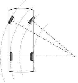
It can also be seen from the diagram that the front corner of the car body requires still more room in order to make the turn. The space taken up by the whole vehicle (and load if applicable) is referred to as the “swept path” of the vehicle.
When representing the swept path of a vehicle in your design, it should now be clear that parallel arcs are only appropriate for a situation where the turn radius is constant, and that the arcs need to be further apart than the width of the vehicle.
Using templates
To assist designers in making adequate allowance for vehicle turning geometry, a number of standard swept-path templates, also known as “tracking curves” are produced. In New Zealand most councils publish one or more swept path templates to be used in their area.
Elements of a tracking curve template
The second diagram is an example of a typical tracking curve which has a number of important features that are described below.

Vehicle
The diagram should be for a vehicle that is appropriate for the design. A common vehicle for residential design is the B85 Car.
The B85 Car is taken from the joint Australian and New Zealand standard AS/NZS2890.1 and is a design vehicle representing 85% of the vehicle fleet. It does not represent any particular vehicle. Other curves commonly used in New Zealand are based on an older New Zealand 90 percentile car which is a similar size to the B85.
It is important to remember that 15% of light vehicles will have a size or turning characteristics worse than the B85 car. When turning into a parking space those larger vehicles can usually be accommodated by some additional manoeuvres (like a three-point-turn). In other situations, like driving around a bend in a driveway, there are no adjustments that can compensate for the larger vehicle, and in those cases larger vehicles simply will not fit. In that type of situation, the appropriate design vehicle to use is the 2890.1 standard B99 design vehicle (which is similar to a van or double-cab ute).
Steering Transitions
It is possible for most vehicles, particularly those with power steering, to have the steering moved while the vehicle is stationary, but this is undesirable for a number of reasons including unreasonable tire and pavement wear, and being difficult for some drivers to accomplish.
Almost all standard templates are based on a circular arc for either the outer front wheel or the outer front corner of the vehicle, with a gradual transition of the steering from straight-ahead to the minimum radius.
It also takes some distance for the steering to be changed from one direction to the other, so for more complex movements involving turns in different directions an extra distance between reverse curves should be allowed for.
While swept-paths for vehicles with stationary steering transitions can be produced these should be restricted to use in limited circumstances, such as domestic parking where the driver is familiar with the particular space and the number of movements per day is relatively low.
Radius and Speed
Most standard templates, particularly those in District Plans, are for the minimum radius that the design vehicle is capable of. It should be remembered that a minimum-radius turn is only possible at very low speed, generally below 10km/hr. If not stated on the diagram the designer should assume that the template is for use at 10km/hr or less. For situations where vehicles are travelling at higher speeds larger radii should be used.
Clearances
A clearance envelope is added to swept-path templates, and is commonly represented by dashed lines.
The clearance envelope is an important element of the template and should not be omitted for design as it allows for:
- differences between the design car and real cars
- variation in the paths steered by different drivers
- some clearance to avoid the vehicle contacting any objects
- components such as rear-view mirrors extending from a vehicle
It is not uncommon to see drawings containing a swept-path taken from a template but with the clearance envelope omitted. That suggests in many cases that the design vehicle, driven precisely, would scrape against objects such as fences, buildings, and other cars.
An appropriate clearance envelope should always be used when designing for vehicles. For light vehicles like cars in low-speed situations a clearance envelope of 300mm on each side of the vehicle is a common minimum. For larger vehicles such as trucks a clearance of between 500mm and 1000mm is typical depending on the speed of the vehicle, the visibility available to the driver for that part of the vehicle, and if the vehicle is being reversed.
Template tips
Custom vehicle paths
A standard vehicle swept-path template can be adapted for a larger radius by understanding that the centre of the turn lies along the line of the rear axle. By rotating the design vehicle around a point, say 15m from the vehicle along the rear axle, the vehicle will trace out the swept path for that radius of turn. The rotation point can be gradually moved to the minimum to represent a gradual change of steering.
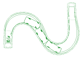
If a vehicle changes direction (either forward-reverse or left-right) make sure to allow space for the transition of the steering from one direction to another. One way of approximating this is to allow at least one vehicle-length of straight travel before starting another turn.
Custom vehicles
Knowing how a standard template is derived, you could map out the swept-path of a vehicle by gradually moving it through a drawing and rotating it about a point along the extension of the rear axle, providing the minimum radius and steering transitions are respected. This is essentially how specialist swept-path analysis software works.
Designing Garages
Designing residential garages using minimum dimensions for parking stalls very often results in a garage that cannot be used by a large proportion of vehicles.
The minimum dimensions for parking stalls, published in places like District Plans and standards, are based on a number of assumptions. A key assumption is that neighbouring vehicles are parked centrally in the adjacent parking stalls, so that a part of the stall on either side can be used for the manoeuvring car. That assumption is not valid when a garage door or other obstruction is present, even if the door is as wide as the minimum dimension for the parking stall. Other assumptions used in the development of the parking dimensions are also absent for a typical residential garage.
As a rule of thumb, we have found that 1m of additional manoeuvring aisle (eg 8m) is often required for typical garages with standard garage doors. There are often ways of reducing that distance.
Can we help?
We have over 30 years of design experience and are specialists in transportation-related design. We have helped to design numerous projects ranging from individual dwellings, through retail, commercial and industrial sites, to road and intersection design; and parking areas from a handful of parking spaces to large parking structures. Our director Wes Edwards is on the Standards Australia committee responsible for the AS/NZS 2890.1 Parking facilities series of standards.
We can provide swept-path templates for a wide variety of standard and custom vehicles, and we can provide bespoke swept-paths for almost any situation. Please contact us to see how we might be able to help you with your next project.
